OSA Department
You are here
ElectroMagnetic Compatibility
Electronic system increasing and dissemination of electromagnetic sources raise the problem of electromagnetic interferences. Various systems under studied have to be treat and need different technique domains as propagation phenomenon, cable coupling, conducting effect, circuit theory, material and composite modelling from low sea propagation, lightning coupling to high frequency interferences. Besides several numerical analysis methods are needed to solve the strong multi-scale geometry of studied system. Our project aims to explain and to solve these electromagnetic couplings by both theoretical and experimental approaches (anechoic and reverberant chambers). For example, the coupling of printed circuit board (PCB) embedded on an airplane with an illumination by transient waves needs to model airplane structure, cable and shielding box of PCB.
Partnerships: CEA, DGA, CNES, DASSAULT AVIATION, THALES, ORANGE LABS, EADS, ASTRIUM, CNES, LEGRAND, GERAC, IEEA, AXESSIM, CISTEME, ALGOTEC…
National research program: ANR (Agence Nationale de la Recherche), PEA (Programme d’étude Amont de la DGA).
Competitivity pole: ELOPSYS
European program: ESA, EUROSTAR
Research areas
Lightning EMC and power transient radiating
Among all research projects in EMC, the lightning effect is the most old study subject since it appears at the beginning of the telecom cable network development. The theoretical analysis of the lightning effect on the hardware systems, buildings and airplanes, etc, is carried out in our laboratory since thirty years. Lightning can disturb electric and electronic systems following two ways:
- The direct lightning return stroke: a preceding leader creates charge onto the channel and subsequently, the return stroke operates on the deposited charge. The lightning channel is connected to a conductive structure or equipment containing electric system. This situation is currently met and studied. An airplane certification is focused on this problem. Strong current propagates on the extern conductor part of the structure. Up to 200kA can be injected by the return stroke.
- The indirect lightning return stroke: the electromagnetic radiation of the lightning channel is studied and its effects on structure are quantified. More recently, the growing interest on the lightning radiation is explained by the increase of the small signal electronic system connected.
The first studies were focused on the analysis of protected circuit like spark gap. Now, research effort is concentrated on the development of numerical modeling to treat the global system on long time. Finite Difference Time Domain is used as full wave method to solve Maxwell-equations. Some problems concern the models of the materials like thin plate of CFC (Carbon Fiber Carbon), conform meshing, the models of the different cables (bare, isolated or shielded thin conductor), skin effect…
Application Domain: Aeronautic, buried structures, building, transport…
Research topics :
- Wave – Structure interaction, current attachment on structure (FDTD Method with our own software TEMSI-FD)
- Complex and realistic cable topology in situ into by a coupling formalism with the FDTD method
- Several cable models performing in lossy media (ground, concrete,…)
- Experimental Design tools applied in aeronautical domain: consideration of uncertainty, variability and ageing of physical parameter set as cable losses, shield connection, geometry, location...
- Massively parallel computation with the simulator TEMSI-FD.
|
A telecom Building with its cable network |
Induced currents on overhead and underground lines during a return stroke attachment on a telecom building (Orange Labs collaboration). |


|
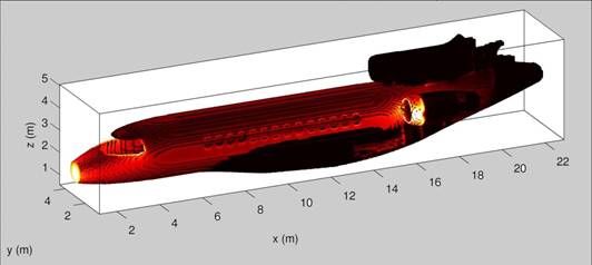
Surface current distribution obtained from a lightning stroke attachment (Dassault-Aviation Partnership) |
|
Cable modeling by a coupling between oblique thin wire formalism and Maxwell’s equations solved by the FDTD method. |
Low Frequency EMC on Satellite
|
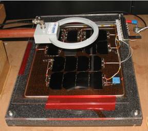
Test Bench |
The low frequency emission of solar panel is an EMC problem for the electromagnetic on-board sensors that are found on scientific satellites. The analysis consists to establish an electrical circuit scheme of the satellite (structure+solar panel). Then, responses can be obtained by solving the problem with SPICE approach. Hence, with elementary electrical dipole spatially distributed and associated current obtained with SPICE resolution, the near field can be calculated by integration of the analytical equations of dipole radiating. The PEEC method (Partial Element Equivalent Circuit) is used to realize the transformation of the satellite to a low frequency equivalent circuit. With this method, the number of lumped elements can increase rapidly. However, techniques of order reduction lead to reduce drastically the problem size because resonance pole beyond to the maximal frequency can be suppressed. |
|
Equivalent scheme of solar panel cells |
|
High Frequency EMC of System
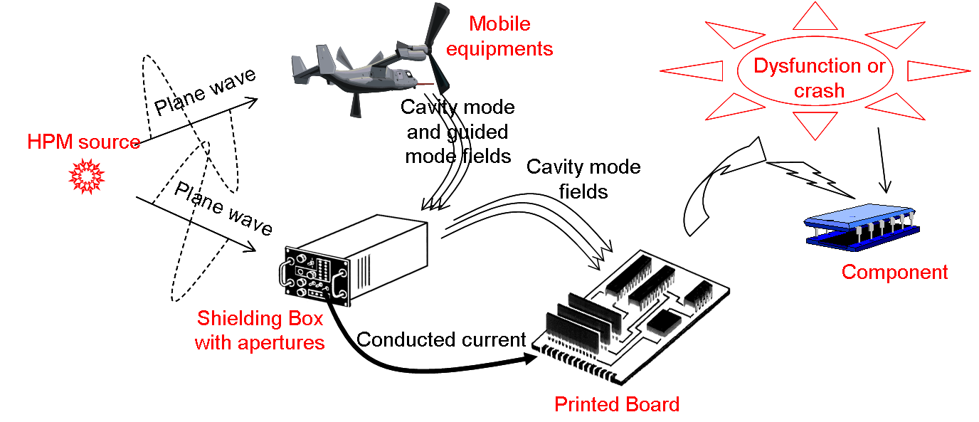
The applied systems in microwave frequency band have a quasi-exponential growth these two last decades. All public equipments are concerned by the high frequency electronic. Beside, device must to cohabit with EM sources having multiform and multi-locations in a closed space. The consequences of the electromagnetic pollution on the integrity signal and the susceptibility of low-power circuit board have to be evaluated and controlled. A new deal concerns the shielding enclosure which material must be reduced to limit the prohibitive cost and burden. In addition the high power microwave (HPM) and the ultra large band pulse (ULB) are new threats that aim the microwave bandwidth. The vulnerability concept is the study of dysfunction risk or crash risk face to the HPM. We develop numerical tool to analyze the propagation way from structure apertures, coupling on cables, conducting way and to the end circuit board coupling. The last link is the component on PCB (Printed Circuit Board) and in particular the low power non-linear lumped. This problem is strongly multi-scale and various numerical techniques are used to solve the different parts (Full wave methods, multi-conductor transmission lines, SPICE, KRON method to convert structure in equivalent circuit…).
Research Topics
- Multiscale analysis, KRON method (network tensorial analysis) and Diakoptic method
- Wave structure coupling
- Vulnerability of Printed Circuit Board (PCB) in situ.
- Circuit Component ElectroMagnetic Compatibility (EMC)
|
Propagation of an electromagnetic wave from a freespace EM source to an electronic component on a PCB into a shielding box. |
|
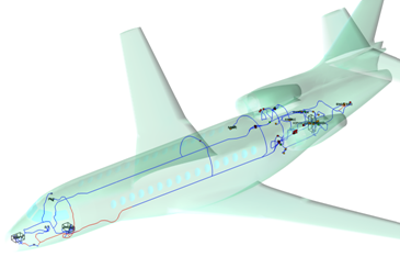
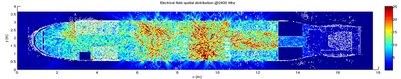
Electrical Field distribution generated by several arbitrarily oriented WIFI sources in FALCON 7X (Dassault-Aviation Partnership) |
Cable EMC
The Cable networks are found in many complex systems into building and transport. With the increasing of the smart electronic system, sensors, and communication technologies, the cable density becomes more and more important. The cable topology constitutes an antenna equivalent system exchanging parasitic wave with the surrounding environment.
Several research topics
- Method of equivalent bundle: Simplification of a cable composed of multiconductors in an unique conductor giving the same behaviour.
- Development of cable models with the thin oblique wire formalism in coupling with Maxwell’s equations (for example: insulated cable, shielding cable, …), multiple scenarios of junction. The main interest is to deal with the simulation of both wire - wave interactions and conducting mode.
- Development of a simulator based on the multiconductor transmission line in the time domain (simulator LAMLIM). Model of cables
- TestBench for cable characterisation, coupling and bulk current injection.
Experimental research and TestBench development
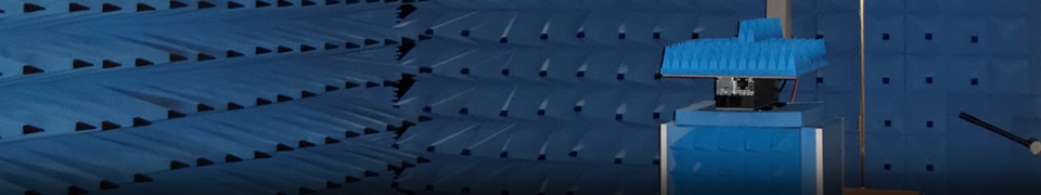
Reverberation chamber
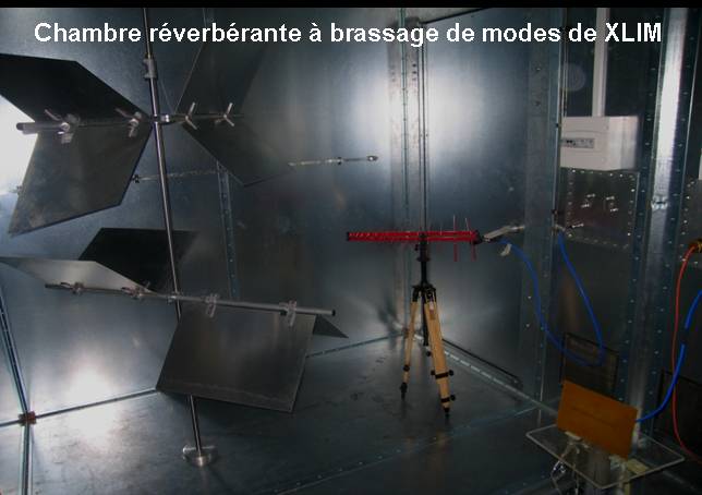
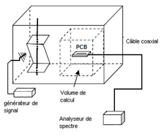
The reverberation chamber (RC) is a new measurement tool that progressively becomes a reference electromagnetic environment for the system immunity test in EMC. Besides system emission measure can operate by the total radiating power technique in the chamber. The RC is an oversized Faraday enclosure where a lot of cavity modes can be generated on narrow frequency band. The stirrer is composed of several blade, each one with unique orientation. The stirrer rotation makes frequency shifting of the modes and also this technique achieves the RC goal: to have a working volume where the probe field is statistically homogeneous and isotropic on large frequency band. Moreover compared to the anechoic chamber, the transmission power in the probe zone is much more important. In this context, immunity test under strong field can be performed.
Research Topic:
- Optimisation procedure of the RC behaviour at low frequencies, reduction of the minimal frequency.
- Statistic analysis
- Investigation on several extensions of the RC as the use of a shield shed containing apertures
- Expertise assessment and measure into RC
 |
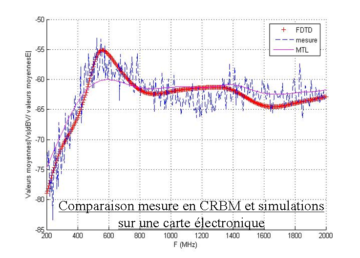
Measure into a reverberant chamber of a PCB and prediction of the RC behaviour by two numerical methods |
 |
Transcient EMC characterisation of non-linear components
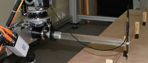
Near Field measurement
|
Testbench for near field measurement |
Numerical analysis and simulator development
The EMC analysis by numerical modelling is a predominant activity of our research project. The various collaborations with industrial and DGA (Army General Direction) lead us to carry out research on many numerical and analytical techniques:
- Analytical technique derived from Sommerfeld equation for very low frequency applied propagation
- PEEC method
- KRON method (tensorial analysis), Diakoptic technique for multiscale analysis
- Full wave method: Finite Difference Time Domain, Finite Volume Time Domain, Galerkin Discontinue Time Domain.
- Multiconductor Transmission Lines method, Method of Moment (MoM)
Concurrently, two electromagnetic simulators receive a great development effort:
- TEMSI-FD: Time Electromagnetic Simulator – Finite Difference is a full wave solver based on the FDTD-3D method.
- LAMLIM: this solver is based on the multiconductor transmission line method in the time domain. It is applied to the analysis of PCB.
TEMSI-FD Simulator
TEMSI-FD is a simulator created in 2002 year. Writing in standard Fortran 90/95 language, this structured code is oriented module and operates now on massively parallel machine thanks to parallel and vector optimization. Hence, OPEN-MP and MPI approaches are used concurrently to perform computation on supercomputer. This is some characteristics of TEMSI-FD:
- Loss materials and perfectly conductors, electric and magnetic dispersive media, volume and surface materials, surface impedance and bilateral impedance, thin wire and thin slot…
- Cable models: straight and oblique wire, isolated wire and buried wire, multiwire junction, wire-metal junction, wire with linear lumped and impedance Z(f) under dipole and quadripole forms.
- Source models: current and voltage sources, network of elementary transparent dipole sources by Huygens principle, plane waves in free space and stratified media, lightning channel.
- Multiple waveforms: gaussian, bi-exponential, Heidler…
- Boundary conditions: ADE – CFS-PML, electric and magnetic wall, Floquet condition.
- Local output: field, voltage, current, impedance, statistic treatments in time and frequency domains
- Far field output: directivity, far field with perfectly ground plane, air-ground interface, stratified media.
An Open-Source version is provided under CECILL-C license. It contains most of functionality of TEMSI-FD. It aims to facilitate collaboration around a same solver and to avoid the multiple rewriting codes (warning: documentation in french). To download the Open-source version, click below
/sites/default/files/opentemsi.tar.gz
Contact: christophe.guiffaut@xlim.fr
LAMLIM Simulator
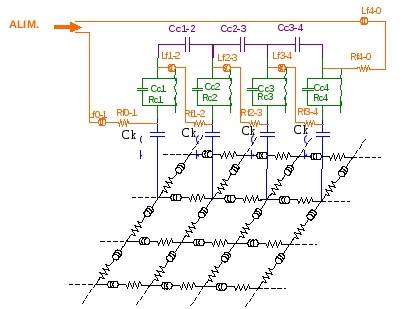
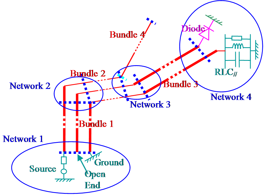
This simulator solves problems of multiconductors topology by the method of multiconductors transmission lines in the time domain. The conductors can be cable type or printed lines on a board. The crosstalk parameters, i.e. the matrix capacitance and inductance are calculated by 2D solver based on the method of moment. A circuit solver solving state variable par Runge-Kutta method allows us to include non-linear components.
|
Bundles and Connexion Networks Description under LAMLIM |
![]()


![]()
 UMR CNRS n°7252
123, avenue Albert Thomas - 87060 LIMOGES CEDEX.
Tél. +33(0) 587 50 67 00 - Fax +33(0) 555 45 76 97