You are here
MACAO
The project-team MACAO gathers a dozen of permanent researchers and lecturers from the research Department MINACOM and a dozen of PhD students. Research activities are directed towards the optimized design of microwave and optoelectronic devices and are organized according to 4 research axes:
- Optimization
- Multiphysical analysis
- Specific technologies
- Advanced synthesis
Optimization
The project-team MACAO develops optimization methods for computer-aided design and set-up of technological processes. These specialized or general techniques are dedicated to driving the design and the realization of devices by minimizing iterations or experiments.
Activities
- Shape optimization
- Data analysis and design of experiments
- Filter identification
Shape optimization
The shape of microwave components is optimized with topology gradient method. The technique allows optimizing the distribution, of metal upon a surface in 2-D, of dielectric material within a volume in 3-D. The property (metal condition or not in 2-D, permittivity value in 3-D) of each topological element is modified for converging iteratively toward the optimal distribution. Convergence is obtained by evaluating the sensitivity of the component with respect to property modification. These research activities are conducted in collaboration with CNES and ANSYS France.
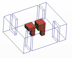
Optimal shape in 3-D
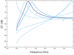
Response iterations with respect to specifications
Filter identification
The synthesis of narrow-band bandpass filters requires a precise dimensioning. Tuning an electromagnetic model or a practical prototype including several tuning elements becomes difficult when the number of parameters increases. Extracting the coupling matrix from the frequency response allows identifying detuned geometrical parameters with respect to an ideal tuning and adjusting iteratively the structure dimensions. These research activities are conducted in collaboration with CNES and INRIA.
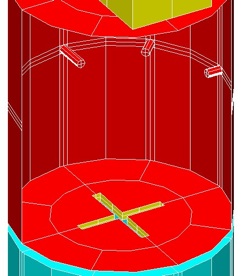
Electromagnetic model of a 6 pole filter
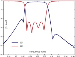
Measurement of the filter after identification based tuning
Multiphysical analysis
The project-team MACAO develops CAD tools based on electromagnetic modelling coupled with other physics laws (circuits, thermics, mechanics) which can take into account many physical phenomena that occur within the device. These multiphysical modelling tools are applied to the characterization and to the design of complex microwave devices.
Activities
- Microwave breakdown in OMUX filters
- Ferroelectric components
- Piezoelectric resonators
- Electrothermal modelling of components
Microwave breakdown in OMUX filters
Output multiplexer (OMUX) filters in communication satellites have to handle high power signals. Under high-power conditions, microwave breakdown phenomena shall occur and deteriorate the circuit. A multiphysical modelling combining fundamental laws of electromagnetics, thermics and plasma physics allows predicting the critical power level for breakdown ignition regarding the geometry of the structure and environment conditions (pressure, composition of gases?). The objective is to dimension the structure for reducing breakdown ignition below a given input power. These research activities are conducted in collaboration with SPCTS, CNES and Thalès Alénia Space.

1-D model of a tuning screw within a cavity
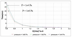
Evolution of breakdown ignition time versus electric field magnitude
Electrothermal modelling of components
Modelling the driver of an electro-optical modulator makes necessary to couple electromagnetic analysis (finite elements in this case) together with circuits laws, in order to take into account active intrinsic models of MMIC chips and and with thermics laws, in order to evaluate thermal dissipation under the chips.
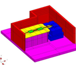
CAD model of a driver
Specific technologies
The project-team MACAO develops original solutions based on specific technologies for the design of microwave components and circuits. Developed approachs aim at optimizing both the performances and the integration of devices working at high frequencies.
Activities
- Design of integrated circuits in LTCC
- Ceramic stereolithography
Design of integrated circuits in LTCC
The new trends of RF systems impose new constraints such as 2D or 3D integration, compactness, tunability, high electric performances... LTCC (Low Temperature Co-fired Ceramic) technology can be a good alternative to other technologies such as classical planar ones or micro-machined silicon. Moreover these multiplayer technologies are now established processes and they are used in many application fields such as military, aerospace, automotive, data processing, telecommunications, and biomedical. Especially as the demand for compact and highly integrated circuits increases, the use of LTCC becomes desirable. In fact, LTCC allows high precision three dimensional (3-D) structuring and vertical integration of the circuits. This 3-D integration approach is a very attractive option to increase density and electrical performances, and to achieve simultaneously cost and size reduction. Several microwave filters have been designed and manufactured in closed collaboration between XLIM laboratory and VTT (Oulu, Finland). The designs of the circuits took place at XLIM laboratory and VTT realized them.
- Waveguide narrow band-pass filter
We first present a surface mountable 41.5GHz waveguide narrow band-pass filter with a ?3dB bandwidth of 7.2%. Its experimental unloaded Q factor is around 350.
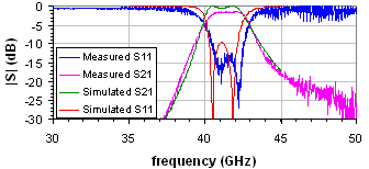
Waveguide filter - S-parameters
- Capacitively loaded cavities for reduced-size band-pass filters
LTCC reduced-size band-pass filters based on capacitively loaded cavities for Q and V band application have been designed and manufactured. The 3D integration of the LTCC technology is used to provide strong capacitive effect to the resonator and then improve circuit compactness. The addition of a capacitive post in the middle of the cavity permits the creation of a capacitive effect. That decreases the functioning frequency and lead to a bulk reduction (at fixed frequency) compared to classical resonant cavities. An example is given for a 57 GHz filter with 3% -3 dB bandwidth. The experimental unloaded Q factor is around 400.
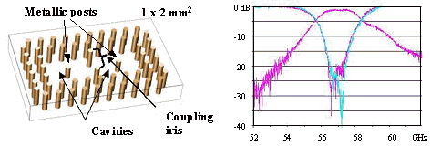
Capacitively loaded cavities - S-parameters
- U-shape 3D resonator for compact size band-pass filter
A very compact 3-D short-circuited resonator has been designed. This resonator is highly integrated (i.e. with a minimal footprint) compared to classical planar resonators and offers great performances at 40 GHz. Its experimental unloaded Q factor is around 330, that is nearly the same than classical planar resonators at Q band. Moreover, the topology of this 3-D resonator presents a great flexibility for the design of original multipole filters. An example of a three pole bandpass filter is presented with 7 % -3 dB bandwidth centered at 38 GHz.
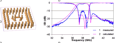
U-shape resonator filter - S-parameters
- High integrated radiant filter
A new design of an hybrid function coupling both filtering and radiating functions has been proposed. In order to fully take advantages of the 3-D integration potential of LTCC, an original structure is presented integrating both the resonator and a patch antenna, functioning at Q band. Encouraging experimental results have been obtained.

High integrated radiant filter
- Hybrid LTCC process. Application to the design of compact S band wired-patch filters
The last example is dedicated to the development of an original new hybrid process mixing both low-permittivity (=7) and high-permittivity (=65) materials in the same substrate. This approach proceeds to be very efficient in decreasing circuits dimensions. Then we proposed an innovative design of a compact C-band filters based on this new technology, with high electrical performances and wide multispurious stop band. Two-pole bandpass filters functioning at a central frequency f0 = 2.52 GHz and f0 = 3.4 GHz with 14 % relative bandwidth and very low insertion losses, were optimized and manufactured successfully, validating the technology and the theoretical approach. The conceived structures are very compact and present excellent frequency isolation, until 5 f0.

Hybrid LTCC compact filter
Ceramic stereolithography
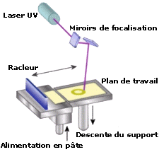
Stereolithography process
This research activity is developed in closed collaboration with the CTTC and SPCTS laboratories. This technology consists of a rapid prototyping technique which allows the fabrication of accurate three dimensional ceramic structures which can not be manufactured by standard shaping means such as pressing or molding. The average manufacturing accuracy is less than 25 um with the current process. The structures described are designed at XLIM lab. and manufactured at CTTC and/or SPCTS laboratories. This technology is based on many ceramic materials such as Alumina (Al2O3) and Zirconia (ZrO2).
- Waveguide in 3D EBG woodpile manufactured by layer-by-layer ceramic stereolithography
An original waveguide located in a woodpile (layer-by-layer) crystal is presented. This 3D Electromagnetic Band Gap (EBG) crystal has been designed, optimized and manufactured in one monolithic piece with Zirconia and with Aluminau by the 3D ceramic stereolithography process. It experimentally exhibits a large complete bandgap superior to 20% and the waveguide located in such woodpile provides a measured 20% bandwidth around 26GHz while keeping a return loss inferior to 10dB. Localized high unloaded quality factor cavities within such crystal have also been studied, designed and measured around 30GHz. First experimental unloaded Q have been measured at 4000 at 30 GHz.
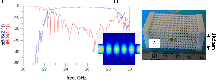
Waveguide in 3-D EBG ceramic woodpile
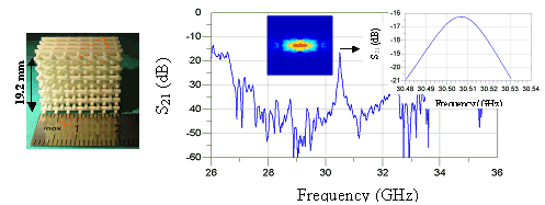
Resonant cavity in 3-D EBG ceramic woodpile
- Innovative shielded high Q alumina resonator
A compact design of a shielded high unloaded Q dielectric resonator has been proposed. The main interests of this work is the use of 3D stereolithography process to manufacture innovative ceramic microwave devices. Thus a resonator, its support and the surrounding cavity is manufactured in one part out of alumina by that process. The measured structure exhibits an unloaded Q of 3900 at 11.88GHz and is free of spurious modes over a 3GHz range.

Shielded high Q alumina resonator - S-parameters
- Submillimeter EBG structure elaborated by micro-stereolithography
The SLA process is based on vectorial polymerization of the objects using galvanometric mirrors lighted by a focalized UV laser beam. The µSLA process is based on the integral illumination of the desired pattern generally using dynamic masks. The SLA process developed at SPCTS lab. uses an Argon ionized UV laser having a 40 µm spot size and allowing average manufacturing definition of about 80 µm. The typical thickness of layers which can be polymerized varies from 25 µm to 100 µm. Our µSLA process uses one Digital Micro-mirror Device (DMDTM, Texas Instrument) as dynamic mask. This DMD is composed of 1024x768 square mirrors (14x14 um2), being individually able to tilt at ±12° along their diagonal by electrostatic forces. The lighting source is a UV lamp with an emission peak at 365nm wavelength corresponding to the absorption band of the photo-initiator. An electronic shutter controls the exposure time. An optical system images on the working surface the pattern defined by the DMD and allows a variable magnification between 0.5 and 2 in order to control the size and the definition of the object. For a unit magnification, the 3D object size can vary from 10 mm to 50 µm. This last value corresponds to the definition of the system. The size of the smallest feature, i.e. 50 µm, is widely larger than the theoretical value, i.e. 14 µm (size of the micro-mirror) because of scattering phenomena. A scraping system and a high resolution elevator allow spreading thin layers of 10 µm thickness with an accuracy of 0.2 µm. The presented structure is composed of a periodic lattice of alumina rods. This part is inserted in a WR 6 waveguide in order to provide a frequency band gap in sub-millimeter wavelength domain. This guide has inner dimensions equal to 0.762 mm by 1.524 mm and works on its fundamental TE10 mode from 110 to 170GHz. A band gap appears in the transmission parameter measurement and a good agreement between experimental and theoretical results is observed.
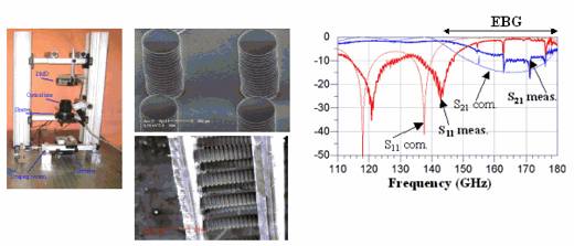
Micro-stereolithography process. Submillimeter EBG periodic structure of alumina rods
Advanced synthesis
The project-team MACAO develops advanced design methods for microwave components and circuits. Developed approaches allow on the one hand to reduce design efforts and costs and on the other hand to improve performances and to simplify system architectures.
Activities
- Multiband filters
- Satellite output multiplexers
- FIlter-antenna sub-systems
Multiband filters
Dual-band filter topology allows to replace diplexed filters for simplifying and improving system integration in space payloads. Designing such a circuit makes necessary to optimize a large number of parameters (33 geometrical parameters in the example) by using identification techniques. These research activities are conducted in collaboration with INRIA and Thalès Alénia Space.
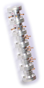
Waveguide dual-band filter
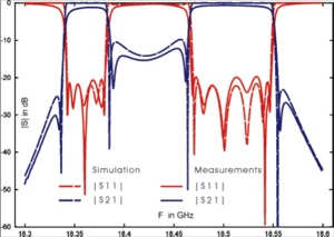
Measurement and simulation
Satellite output multiplexers
Satellite output multiplexers consist in a large number of filter channels connected to a common waveguide. Synthesising these circuits makes necessary to take into account precisely parasitic couplings that occur between channels and to set up a procedure and a flexible CAD model which can handle and optimize a large number of parameters (typically a hundred). These research activities are conducted in collaboration with Thalès Alénia Space.
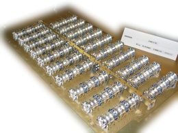
20 channel OMUX (Thalès Alénia Space)
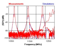
Measurement and simulation of 3 channel OMUX
Filter-antenna subsystems
Synthesis of sub-systems combining several signal processing functions is generally done by designing each circuit independantly. Each circuit is designed with respect to a common reference impedance, allowing to match each circuit to its neighbours while assembling the sub-systems. However, the mutual synthesis of two circuits with respect to an optimal impedance can simplify the architecture and improve the performances of the sub-system globally. These research activities are conducted in collaboration with the research Department OSA.
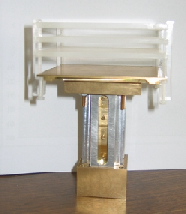
Filter-antenna sub-system
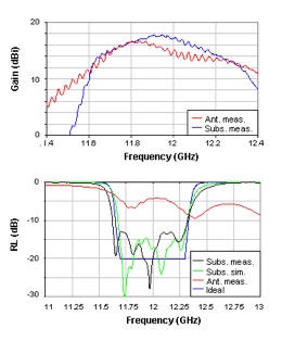
Return loss and gain of the sub-system



 UMR CNRS n°7252